Starting a GPU-GUI library in Odin with SDL2 and Metal
Setting up the project structure and the Metal rendering pipeline
This is part of a series of hands-on tutorials. I will not be sharing copy-pasteable code; only screenshots. The idea is to get the reader to write their own code and run their own experiments.
In the first three episodes, we explored signed distance functions and saw how they can serve as the basic building block for a GUI library.
In this episode, we’ll finally begin writing code for the project.
Here’s the answer to the homework from the previous episode:
Project Structure
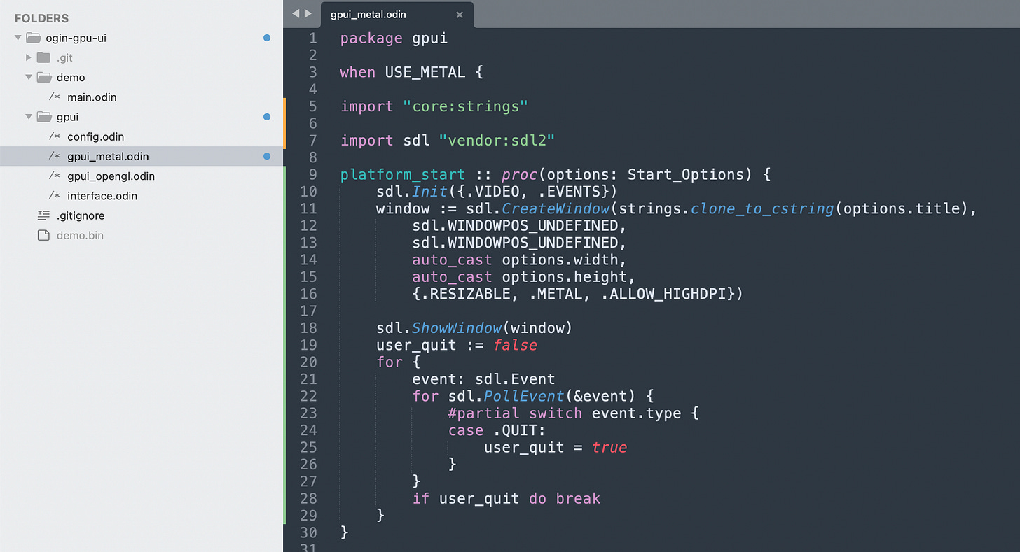
Odin code is organized into packages, where each package is the set of odin files contained within a directory. Any package can be used as the entry point as long as it has a `main` procedure defined.
For now I’ll put the “library” code in a `gpui` directory, and I’ll have another directory for a `demo` program which we will execute to test things out.
The demo code for now attempts to draw two rectangles. The procedure draw_rect takes two parameters: placement and color. Both a `float4` value.
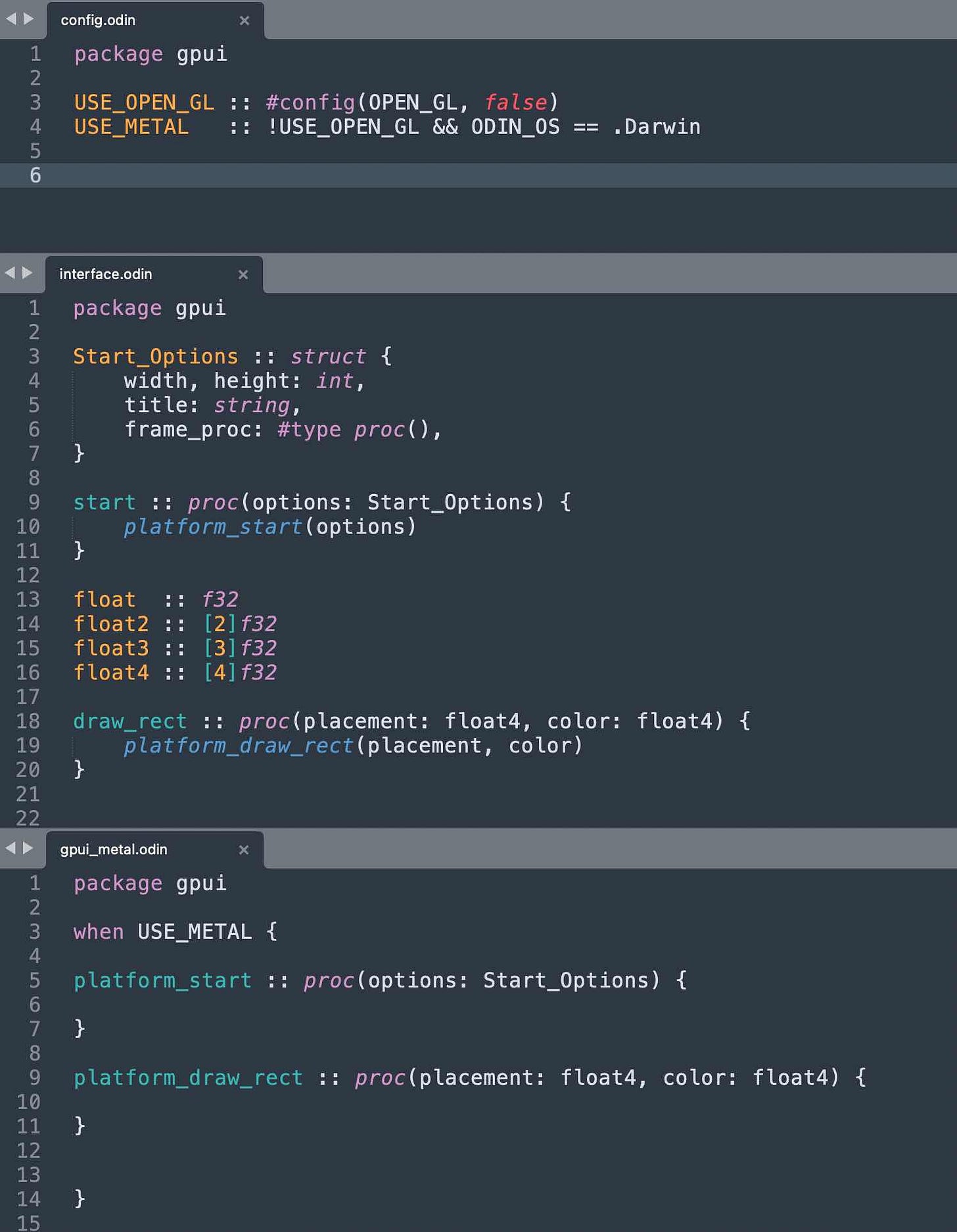
Since I know we’ll have a metal and an opengl backend, I’ll define some boolean constants that we can use for conditional compilation.
I’ll define the platform-agnostic interface as regular functions that just call to a `platform_xxxxx` procedure.
Now with this kind of setup, we can run the demo package. It does nothing.
To make it do something, we need to fill in the code for the platform_start and platfrom_draw_rect in the metal implementation.
We’ll start with boilerplate SDL code.
Empty SDL Window
The odin compiler ships with bindings for SDL2, a popular platform abstraction library. It makes it fairly easy to create a window and start an event loop. The code should work on all platforms without much modification.
Now when we run the demo program, we get an empty black window that can be dragged around.
Metal Rendering Pipeline
The code for setting up the rendering pipeline in most modern graphics APIs looks really confusing, specially to beginners like myself.
The official guide/tutorial for Metal can be found here:
https://developer.apple.com/documentation/metal/using_a_render_pipeline_to_render_primitives
Now, what we want to do at the end of the day is send some rectangle coordinates from the user code all the way to the GPU.
We’ll deal with the rendering pipeline boilerplate as just that: boilerplate. People who do advanced 3D rendering engines will probably customize many aspects of this pipeline, but for us, we’ll just take it as-is.
However, as much as possible, I’ll try to introduce this boilerplate in stages.
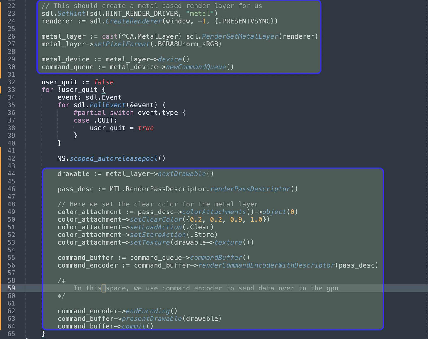
To start with, we’ll just set things up so that we clear the screen with a specific color. No shaders. No data transfer.
Since we’re dealing with objc managed objects, we’ll use the autoreleasepool inside the loop, to avoid all the manual `object->release()` calls.
Here’s what appears to be a decent minimal example for doing what we want in Objective C: gist: Minimal C SDL2 Metal example
I cannot tell you that I understand what the color attachment is, but as far as I can tell it appears to be the render target.
Now, when we run the code, we get a screen with the color described by the RGB values (0.2, 0.2, 0.9)
If you are looking to understand more about what’s going on here, in addition to the official guide I posted above, this appears to be a very good resource as well:
Donald Pinckney's Metal 3D Graphics Part 1: Basic Rendering
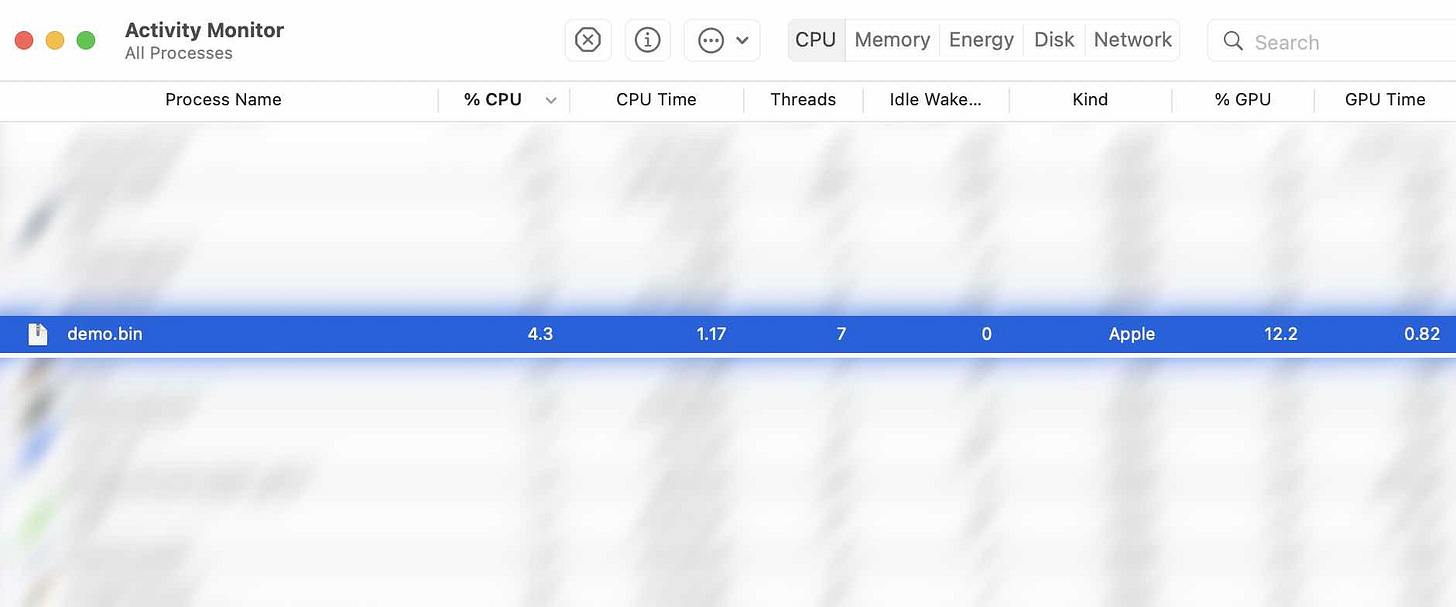
Inspecting the Activity Monitor, I notice that our little program is consuming about 4% of CPU and 10% of GPU. I’m not really sure what that means. We’re not really doing any computation on the GPU as far as I can tell.
Fow now I will not bother trying to fix this. However, it does serve as a baseline that we can use to measure against future iterations on our code. If GPU usage jumps to 50% then we can reasonably say that our code is taking a big toll on the GPU. If however it stays around 10% then we’ll just assume that everything is fine and dandy.
Setting up the shaders
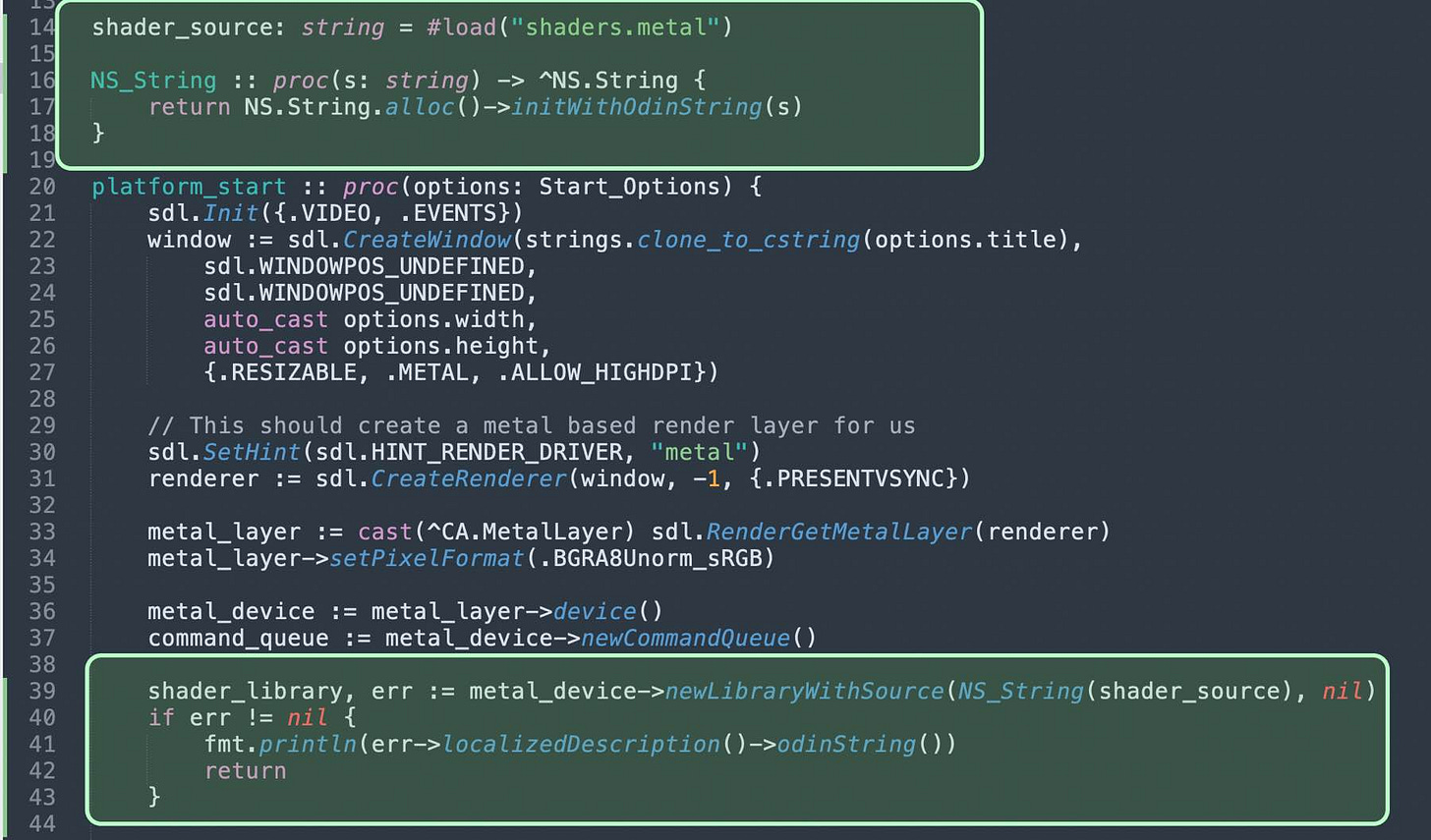
I created an empty shader file, and added a little bit of code to load it during the startup phase (before the game loop)
The first line shows a feature of the odin compiler, where the contents of a file are embedded into the program via the `#load` directive.
Now, the code compiles and runs fine. It doesn’t do anything new per se. But, it does have functionality to report shader errors.
If I put some bogus content in the shader file, then I get the equivalent of a compiler error message. Here’s what I get when I just put the letter ‘x’:
This might appear like an odin compiler error, but it’s not. The building of the demo program is not failing. It’s working. The program runs, loads the shader code, encounters an error, and reports it (line 41) then basically exits (line 42).
Before writing the actual shader code, we need some wiring code:
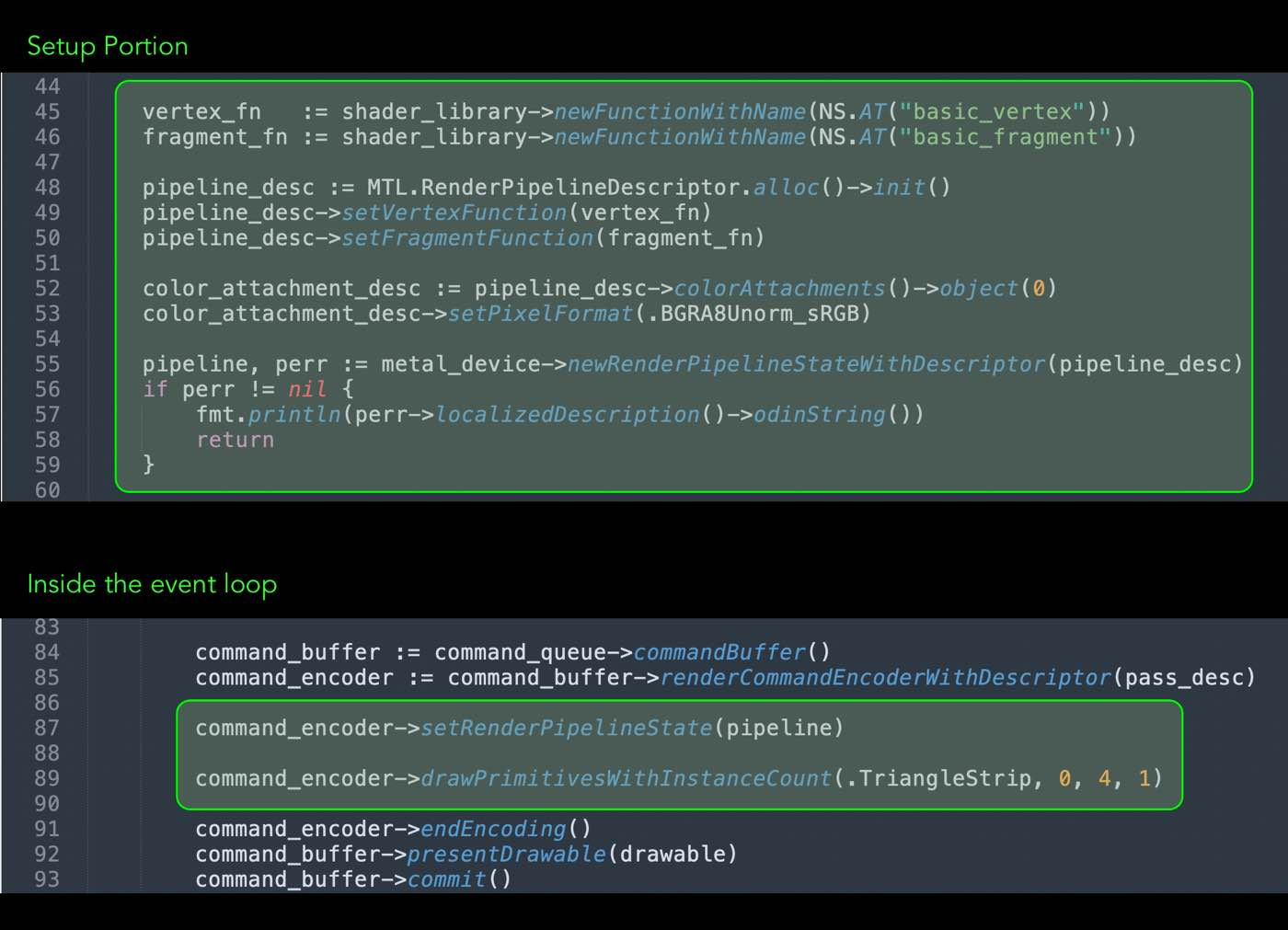
I can’t claim that I understand exactly what’s going on here, but from the looks of it, a shader is only applicable to a “render pipeline state”, which the following code sets up. It basically specifies the name for the vertex function, the name for the fragment function, and the pixel format for the “color attachment”.
Within the event loop, we add one line to use this render pipeline state with the command encoder, and one line to send one command to draw some triangles.
The command says to draw one instance of a triangle strip that has four vertices
Notice we are not sending any data to the GPU. We’re just telling it to draw a triangle strip. The rendering pipeline will invoke our vertex function once for each vertex. Once it gets all the vertex coordinates, it will determine where the resulting triangle strip should be rendered to the screen, and for each pixel, it will call the fragment function.
This is a good time to reference an important bit from the official Metal guide link I posted above:
I want to draw a rectangle in the middle of the screen with some interesting color that is different from the background color we’re using so far. This is to verify that things are working properly.
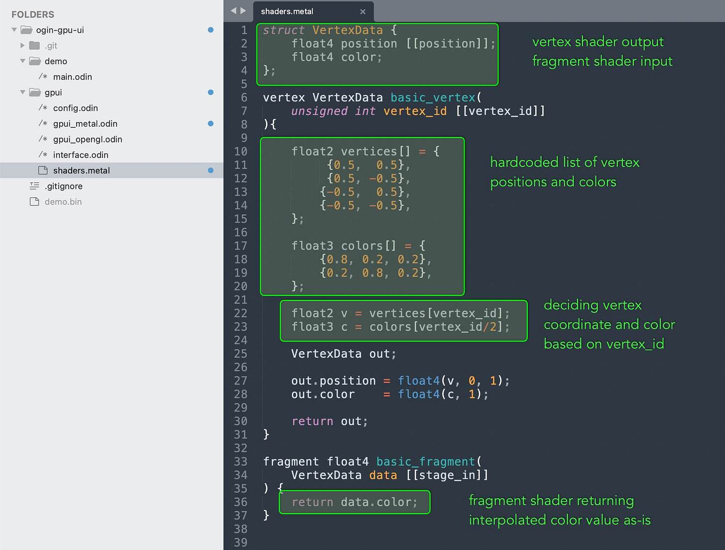
Let’s take a look at the shader code. It’s going to be different than what we’ve seen so far in shadertoy. For one thing, this is the metal shader language; it has a different way of specifying inputs and outputs. For another thing, this includes both a fragment shader and a vertex shader, where as we only saw the fragment shader in shadertoy.
There’s a lot to cover here, but I don’t think that we need to turn this into a tutorial on the Metal Shader Language. I’m not qualified to give such a tutorial anyway. You better consult the official reference manual:
Metal Shader Language Specification
There are however a few things to pay attention to.
One is the use of special [[tags]] to denote struct fields and function parameters that have a special meaning. You can actually add more parameters to the shader functions. When we pass data from the CPU to the GPU we’ll use some special tag to denote that.
For our vertex shader, notice how the values for vertex coordinates are basically hardcoded. They return a rectangle that is half the screen size and positioned in the middle. The official guide I posted above explains the coordinate system. Here’s a relevant screenshot:
The other important thing to notice is that for each vertex we’re not just returning the coordinates (marked by the [[position]] tag), but we can assign any number of float attributes. These attributes will be interpolated for each pixel as they pass to the fragment shader. This interpolation is done by the GPU for us. We don’t need to do anything to make it happen. Here we’ve assigned a color to each vertex, but we can also assign other things.
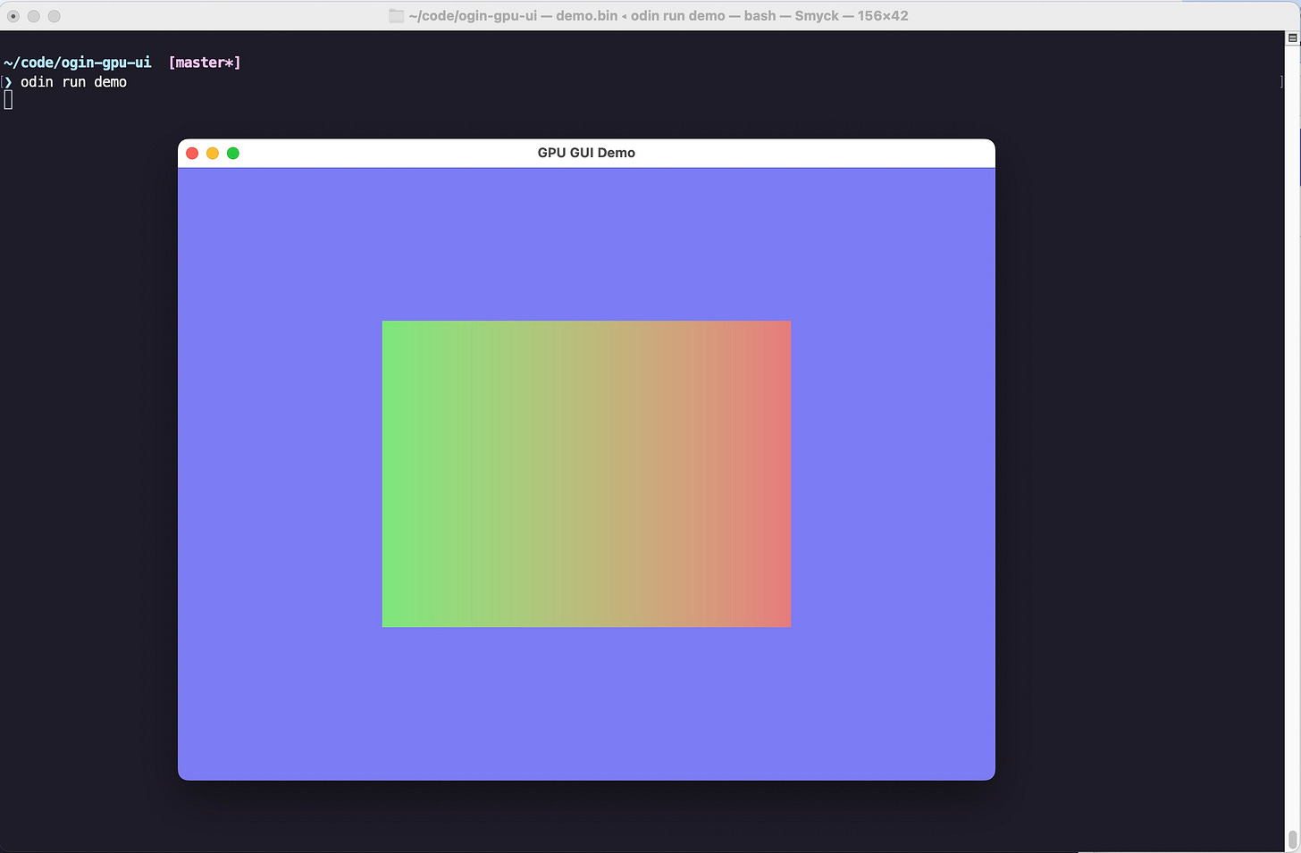
Now, when we run the program, we get the following result:
We have our blue-ish clear color in the background, and we have a rectangle in the middle with a color gradient decided by the vertex and fragment shaders.
Sending data from the CPU to the GPU
The basic concept as far as I could understood it is rather simple. It’s basically a byte buffer assigned a slot number. There are several ways to manage it from the CPU-side, but on the GPU side as far as I can tell you recieve it by annotating a function parameter with `[[buffer(N)]]`, where N is the slot number.
Since it’s just a byte buffer, you have to make sure the layout is interpreted correctly in the shader code. You have to know the size of the data you’re sending. If you send float64 from the CPU but then attempt to read it as float32, you will be in trouble. If you send structs then the padding/alignment might become an issue if you’re not careful.
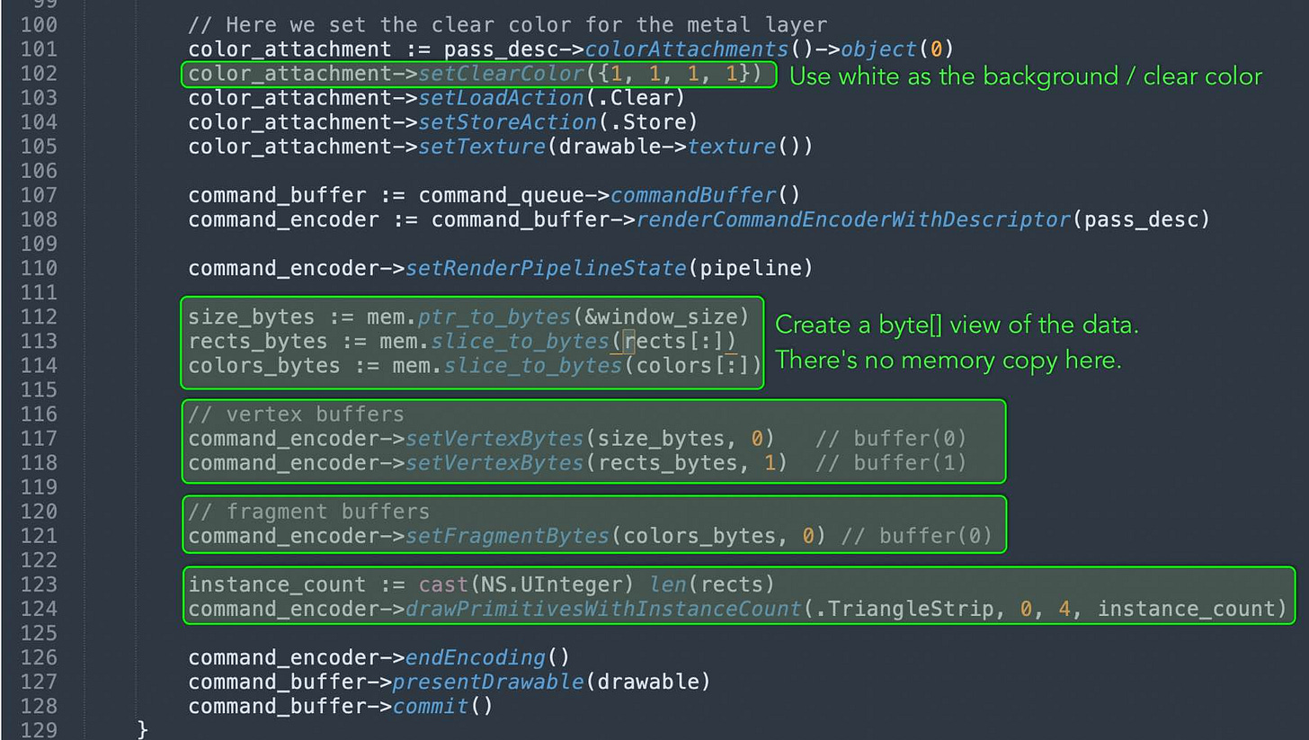
The simplest way to send data is with the setVertexBytes method. The atIndex parameter is the slot number.
There are two pieces of data I want to send: One is the screen resolution (more precisely, the dimensions of the window or the rendering target, in pixels). The other is the list of rectangle data with placement and color.
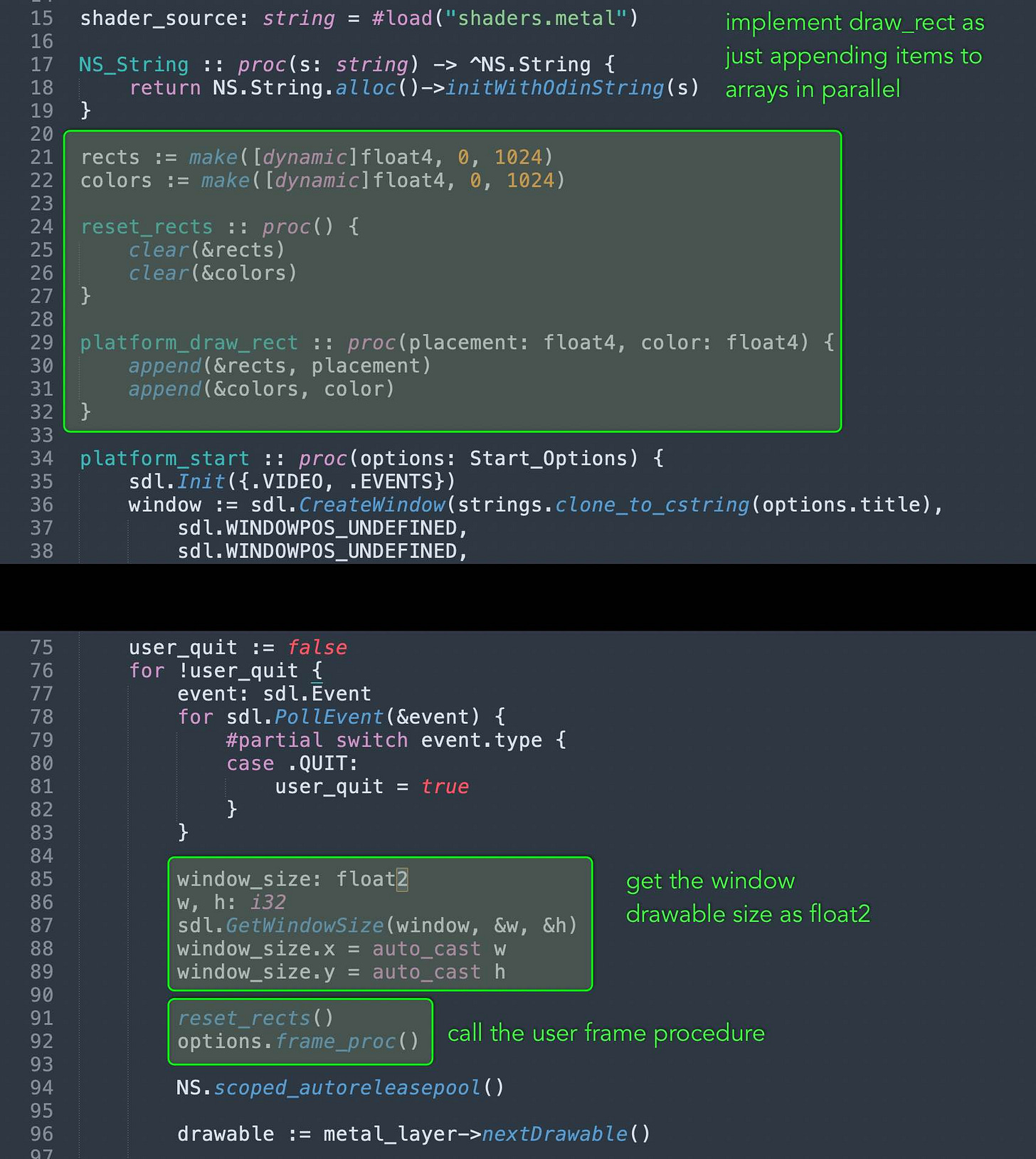
We haven’t yet defined the rectangle data. We just have an empty procedure to accept them as inputs from the user code. Let’s fill in some code:
Now that we have the implementation for draw_rects, we can start actually running the user provided frame_proc that would use draw_rects to place rectangles on the screen.
I decided to split the rectangle data into separate but parallel arrays. The reason for that is the rect position data is of interest to the vertex shader, but the color data is useless to the vertex shader; it’s only going to be used by the fragment shader.
Now we have the data we want to send to the GPU ready, so we can start actually sending it:
The code is more or less pretty straight forward.
Now, we can update the shader code to work with the incoming data.
Receiving data on the GPU side
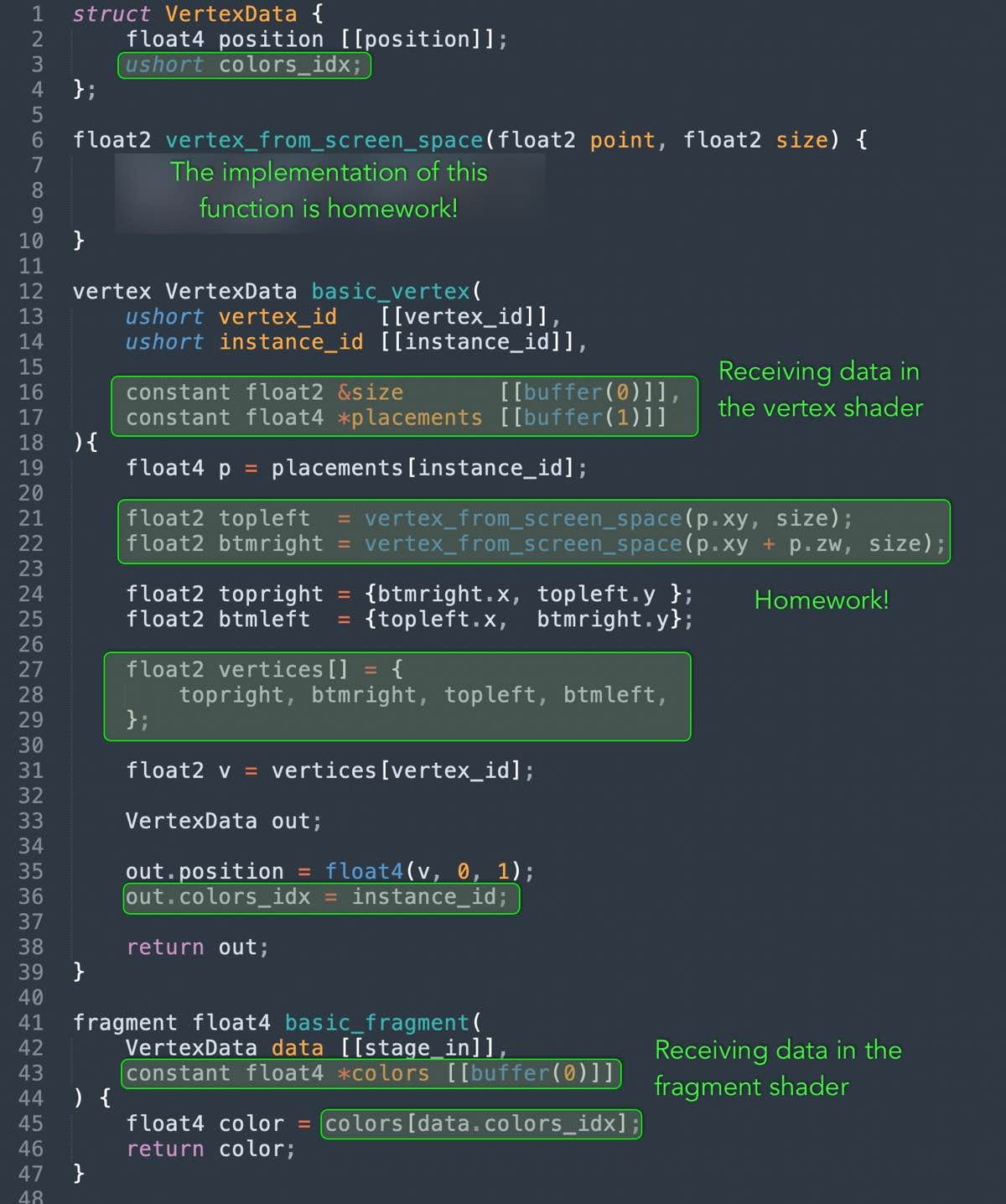
As I mentioned, the way to receive data on the GPU is to add new parameters to the shader functions and annotate them with `[[buffer(N)]]`. But before we see that, we need to consider what the shader code needs to do.
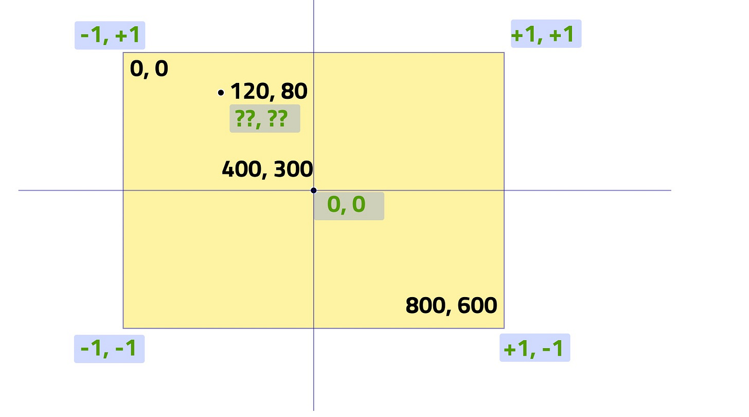
The original shader code just returns a rectangle with hardcoded coordinates, but now we must recieve the coordinates from the user code. The user code specifies coordinates in screen space with the top-left corner being the 0,0 point, the x-axis advancing from left to right, and the y-axis advancing from top to bottom.
So we need to figure out how to translate from screen space to vertex space.
The solution so this problem is left as homework. It should not be too difficult if you’ve been following along so far.
With that said, here’s the updated shader code:
With that in place, the demo program now works!
As another test, we’ll add a rectangle that follows the cursor:
We update the frame proc to take some data parameter and include the mouse position in it. The other details are trivial enough that I feel it’s ok to leave it to the reader’s imagination.
frame_proc :: proc(data: gpui.Frame_Data) {
	gpui.draw_rect({50, 50, 200, 80}, {0.2, 0.2, 0.8, 1})
	gpui.draw_rect({300, 50, 200, 80}, {0.2, 0.8, 0.2, 1})
	gpui.draw_rect({data.mouse.x, data.mouse.y, 30, 30}, {0.9, 0.3, 0.3, 1})
}
You may notice that the mouse driven rect appears above the other two rects, even though they all have the same z coordinate of 0.
It appears the only determining factor here is the order in which we draw them. If we change the ordering of the draw_rect calls, the layering order changes accordingly.
Setting Blending Mode Properly
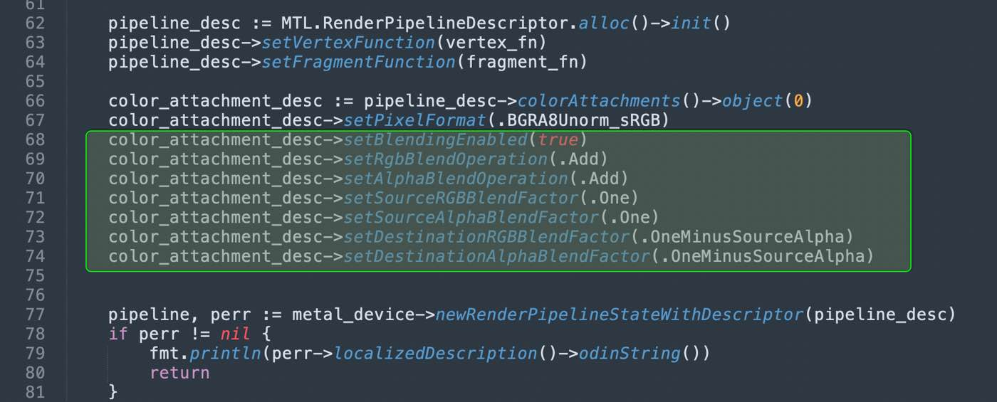
If we change the colors of the rectangles to have 0.8 alpha channel instead of 1, we would expect to see some transparency effect, but when we actually try it, that’s not what we see!
The solution to this is setting the blending mode on the pipeline state descriptor’s color attachment object. As far as I can understand, this achieves the same blending effect as what we did in shadertoy with the composite function.
Just adding these lines of code fixes the problem. No further changes needed.
With this, we have achieved our first objective: creating an API that draws rectangles to the screen using the GPU.
Although a lot of pipeline setup code appears to be impenetrable magic incantations, I tried to build them up incrementally, so that we at least know what each portion does, even if we don’t grok everything about how or why.
If you would like to follow along, but your OS is Windows, I encourage you to learn how to achieve a similar kind of setup in Direct3D. If your OS is Linux, I encourage you to explore doing this setup in Vulkan.
In the next episode, I will try to replicate the same implementation, but for OpenGL. Although it’s not the best API as far as I can tell, at least it does work on all platforms, more or less.
The remainder of the series will focus on Metal shader code, and I believe most of what we will do should be easy to translate to other APIs, given that we have the initial setup taken care of.
See you next time.
P.S. I made a spelling mistake and named the project directory “ogin-” instead of “odin-”. If you look at all the terminal screenshots and videos, it’s there in all of them.






It appears that you are using premultiplied alpha blending, but it looks like the colors you're sending to the GPU are not premultiplied, unless I missed something.